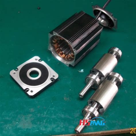
Permanent magnet rotor e1655961736623.jpeg.
A permanent magnet synchronous generator is a generator where the excitation field is provided by a permanent magnet instead of a coil. The term synchronous refers here to the fact that the rotor and magnetic field rotate with the same speed, because the magnetic field is generated through a shaft mounted permanent magnet mechanism and current is induced into the stationary armature.
Oct 14, 2002 · The most important magnet layouts in rotors of hybrid permanent-magnet synchronous machines (PMSM) for electric vehicles are compared in a variety of characteristics. The effect of different rotor designs on the vehicle performance and energy consumption is evaluated for a small battery electric vehicle (BEV) for different drive cycles. The research is devoted to the investigation of NdFeB permanent magnet (PM) based synchronous generators with non-overlapping concentrated windings. The rotor of such …This paper compares two flux-switching machines, namely, one stator permanent magnet flux-switching machine and one rotor permanent magnet flux …Dec 15, 2023 · Interior permanent magnet (IPM) motors in traction applications often employ discrete rotor skewing constructions to reduce torsional excitations and back-EMF harmonics. Although skewing is very effective in reducing cogging torque, the impact on torque ripple is not well understood and can vary significantly over the operating envelope of a motor. Skewing also leads to the creation of a non ... This paper proposes a new structure of the dual-rotor hybrid-excited axial-flux permanent magnet vernier machine (DR-HEAFPMVM) with the modular stator and the consequent-pole PM (CPM) rotor for low-speed, high torque density applications such as in-wheel electric vehicles. The tooth-wound non-overlapping armature windings and direct …
Among them, the NS type rotor has a structure in which the permanent magnetization direction of the two-sided rotor is opposite. One rotor permanent magnet magnetic flux flow to the opposite rotor. The advantage is that there is no magnetic flux flowing through the Stator back-yoke, making the design easier. Furthermore, by …The SPMSM has the permanent magnets fixed on the surface of the rotor leading to a symmetrical radial air-gap reluctance path between the rotor and the stator core. The IPMSM has the permanent magnets inserted inside the rotor core leading to a non-symmetrical radial air-gap reluctance path between the rotor and the stator core.
This paper proposes a two-phase radial flux brushless DC motor comprising a rotor decorated with hybrid permanent magnet (PM) material, i.e., rare-earth NdFeB magnets combined with ferrite magnets. The rare-earth NdFeB magnets are used on the surface, and ferrite magnets in the spoke-type configuration. The combined surface and …addition to the magnet torque, thus improving the efficiency. In addition, the IPMSMs provide more rotor robustness as magnets are embedded in the rotor laminations; hence, no additional retention sleeving is required. Various IPMSM technologies have been studied in the literature. In [3], the V-shape, the U-shape, the spoke-type and the
In this study, an analytical model is established to efficiently compute the magnetic field and unbalanced magnetic pull (UMP) in axial-flux permanent-magnet motors (AFPMMs). The effects of stator …A commercial traction motor (Prius 2010), designed with Nd-Fe-B magnets for maximum power 60 kW and maximum speed 13,500 rpm, is used as the baseline for comparing the HRMM design. The HRMM design shows comparable performance with the commercial design for the given speed range with ~ 50% reduction in critical rare earth …Permanent magnet generator (PMG) for vehicles has attracted more and more attention because of its high efficiency, high power density, and high reliability. However, the weak main air-gap magnetic field can affect the output performance and the normal use of electrical equipment. Aiming at the problem, this paper took the rotor …Arnold produces high performance permanent magnet motor components and sub-assemblies for aerospace and defense, industrial, automotive, and motorsport applications, such as: KERS — Kinetic Energy Recovery System, which includes a composite sleeved RECOMA® SmCo magnet rotor for a 50,000+ RPM, 100KW+ system
1 Introduction. Flux-switching permanent-magnet (FSPM) motors have advantages such as high-power and -torque density, high efficiency and simple and robust mechanical structure in the rotor [1-4].These motors have bipolar flux linkage and sinusoidal back-electromotive force (EMF) [].In FSPM motors, because of the placement of …
This study proposes design procedures for the permanent-magnet-biased magnetic bearings (PEMBs) in rotor systems. Many aspects of designing magnetic …
Permanent magnet motor. Schematic of a permanent magnet motor. A permanent magnet motor is a type of electric motor that uses permanent magnets for the field excitation and a wound armature. The permanent magnets can either be stationary or rotating; interior or exterior to the armature for a radial flux machine or layered with the armature for ... The permanent magnet motor tends to have larger step angles, 7.5° or 15°, than the variable reluctance motor. The hybrid motor typically has 200 rotor teeth and rotates at 1.8° step angles. They have high static and dynamic torque and can run at very high step rates. As a consequence they are very widely used. Permanent magnet traction motor has the advantages of high efficiency, high power density, high torque density and quick dynamic response, which has been widely used in the traction field of electric vehicle. The high-performance control of permanent magnet traction motor depends on accurate rotor position information, which is usually …This paper overviews high-speed permanent magnet (HSPM) machines, accounting for stator structures, winding configurations, rotor constructions, and parasitic effects. Firstly, single-phase and three-phase PM machines are introduced for high-speed applications. Secondly, for three-phase HSPM machines, applications, advantages, and …1. Introduction. At present, the low-speed high-torque transmission system has vast application prospects in the application fields of ship propulsion, lifting, mining and oil field exploitation [1].Permanent magnet motors can maintain good performance in a wide range of load changes, so they have received extensive attention in low-speed and large …
Oct 6, 2023 · The rotor of the HSPMSM adopts a solid cylindrical permanent magnet rotor with the parallel magnetization of two poles. The excitation magnetic field of the permanent magnet is a standard sinusoidal magnetic field, which can provide a large magnetic potential, which is convenient for the design of large air gaps and is conducive to ventilation and heat dissipation. Aug 17, 2022 · For high-speed permanent magnet machines (HSPMMs), two different rotor structures are widely used: surface-mounted permanent magnet (SPM) and interior permanent magnet (IPM). The two different rotor structures have a large impact on the comprehensive performance in multiple physical fields of HSPMMs, including mechanical stress, electromagnetic characteristics, and temperature distribution ... Feb 9, 2018 · Electric machines with permanent magnet rotors are becoming increasingly popular due to the high power density that they offer relative to other configurations. Where the speed of rotation is high, the magnets are typically mounted on the surface of the rotor and retained by an outer sleeve. In the literature, a variety of analytical models have been proposed to aid the mechanical design ... Among them, the NS type rotor has a structure in which the permanent magnetization direction of the two-sided rotor is opposite. One rotor permanent magnet magnetic flux flow to the opposite rotor. The advantage is that there is no magnetic flux flowing through the Stator back-yoke, making the design easier. Furthermore, by …External rotors of “outrunner” type. Rotors with additional bandage (Polyglas, Kevlar, carbon) Rotors with protecting sleeve. Contact us. Jan Kratochvil ml. +420 607 570 823 [email protected]. We will be happy to cooperate on development and manufacturing of rotors with permanent magnets, please contact our specialist. Leave …
an interior permanent magnet (PM) synchronous motor into a hybrid motor. This hybrid technology uses a conventional induction rotor cage to bring the motor up to its slip speed just like any traditional induction motor. Once at slip speed, the powerful interior magnets pull the rotor into true synchronous speed with the rotating magnetic field.In order to address these issues, a 2-DOF surface permanent magnet spherical motor with a new mechanical design for the movement of the rotor with a large tilt angle of ±45° was designed, simulated, produced and tested in this paper. The motor consisted of a 4-pole permanent magnet rotor and a 3-block stator with 18 coils.
The advantages of choosing Sintex® magnetic rotors are as follows: Patented solutions. Complete solutions. 100% sealed enclosure – can run as wet runner. Corrosion-resistant materials. High efficiency / low energy loss. Maintenance-free. Long service life. …Oct 6, 2023 · The rotor of the HSPMSM adopts a solid cylindrical permanent magnet rotor with the parallel magnetization of two poles. The excitation magnetic field of the permanent magnet is a standard sinusoidal magnetic field, which can provide a large magnetic potential, which is convenient for the design of large air gaps and is conducive to ventilation and heat dissipation. 2 Rotor system dynamics modelling of high-speed PM motor 2.1 Support characteristics of active magnetic bearings (AMBs) To make the rotor reach a high speed, the use of non-contact magnetic bearing or air bearing is required. First the rotor critical speed analysis needs to study the support characteristics of rotor-bearing system.Dec 15, 2023 · Interior permanent magnet (IPM) motors in traction applications often employ discrete rotor skewing constructions to reduce torsional excitations and back-EMF harmonics. Although skewing is very effective in reducing cogging torque, the impact on torque ripple is not well understood and can vary significantly over the operating envelope of a motor. Skewing also leads to the creation of a non ... Axial-flux permanent magnet (AFPM) motors have been attracting great interest due to their key advantages of high-torque density and compact structure. Concentrated windings are commonly used for AFPM motors since they significantly reduce the radial length of the end windings. This paper proposes a novel double-sided stator …Measure Skewing Angle. MagScope software makes it easier than ever to measure the skewing angle of skewed permanent magnet rotors, enabling the detection of skewing angle deviations. The right figure shows an example of the step skew on an IPM (Interior Permanent Magnet) rotor, represented in a cross-section graph with automatic zero-crossing ... Since the pole arc coefficient of the rotor permanent magnet is 0.5, according to Ref. 28, the magnetomotive force generated by the permanent magnet is equal to that generated by the adjacent FMP.This paper proposes a new design method for sleeve thickness and interference based on a multi-dimensional visualization algorithm that overcomes difficulties in solving. The contact pressure between the rotor core and the permanent magnet, the maximum equivalent Mises stress of the permanent magnet, and the maximum …Understanding permanent magnet motors. A permanent magnet (PM) motor is an ac motor that uses magnets imbedded into or …
Permanent-magnet motors can be designed to operate at synchronous speed from a supply of constant voltage and frequency. The magnets are embedded in the rotor iron, and a damper winding is placed in slots in the rotor surface to provide starting capability. Such a motor does not, however, have means of controlling the stator power factor.
Jun 23, 2022 · The rotor overtemperature caused by losses is one of the important issues for the high-speed electrical machine. This paper focuses on the rotor loss analysis and CFD-thermal coupling evaluation for 105 kW, 36,000 r/min HSPMSM. Three types of sleeve materials as carbon-fiber, Titanium alloy, and stainless steel are introduced in this paper, researching the effects of sleeve conductivity ...
an interior permanent magnet (PM) synchronous motor into a hybrid motor. This hybrid technology uses a conventional induction rotor cage to bring the motor up to its slip speed just like any traditional induction motor. Once at slip speed, the powerful interior magnets pull the rotor into true synchronous speed with the rotating magnetic field.2.1 Electrical Characteristics. The equivalent circuit of a PMDC motor is shown in Fig. 1. The supply voltage and the current are given. The circuit consists of an induced voltage (Vi) in series with an armature resistor (Rarm) and inductance (Larm). The rotation of the ux generates the induced voltage.In this study, we performed an electromagnetic characteristic analysis of a permanent magnet synchronous machine considering the current waveform based on static rotor eccentricity. First, the characteristics of the back electromotive force were analyzed through the no-load analysis of the analysis model according to static rotor …When the rotor magnets are placed inside the rotor iron in PMSM, the machine is called interior permanent magnet (IPM) . In this case, the magnetic reluctance is not uniform as it was for SM-PMSM. So, the self-inductance value of the stator will depend on the rotor position and, consequently, there will be nonzero reluctance torque in addition to the …In this work, different analytical methods for calculating the mechanical stresses in the rotors of permanent magnet machines are presented. The focus is on interior permanent magnet machines. First, an overview of eight different methods from the literature is given. Specific differences are pointed out, and a brief summary of the …In order to get rid of the bulky and lossy differential gears and to enhance the system robustness, the magnetic differential (MagD) system is proposed after the mechanical differential (MechD) and electronic differential (ElecD) systems. The MagD system is mainly composed of the double-rotor (DR) stator-permanent-magnet (PM) …This paper presents an analysis of torque pulsation with respect to the rotor rib shape in an interior permanent magnet motors (IPMs) and the type of magnet materials. The effects of three parameters, the angle and length of the flux barrier and the residual flux density of the PM, are studied using the response surface methodology. …Permanent-Magnet Motors Wen L. Soong, Member, IEEE, and Nesimi Ertugrul, Member, IEEE Abstract— This paper compares the field-weakening perfor-mance under rated and overload conditions of synchronous reluctance and interior permanent-magnet motors against that of a baseline 2.2-kW induction machine. Four prototype rotors basedNon−Magnetic Rotor Core Rotor Magnets Rotor Pole Pieces Figure 2: Axial View of a Flux Concentrating Motor The geometry of one type of internal magnet motor is shown …Mar 16, 2015 · A post-assembly magnetizing fixture has been designed and successfully used to magnetize the rotor of a 100 kW high speed permanent magnet synchronous motor. The rotor is a solid cylinder with outer diameter of 80 mm and total length of 515 mm. The permanent magnet material is samarium-cobalt (Sm 2 Co 17) with saturation magnetizing field of 6 ... This paper proposes a two-phase radial flux brushless DC motor comprising a rotor decorated with hybrid permanent magnet (PM) material, i.e., rare-earth NdFeB magnets combined with ferrite magnets. The rare-earth NdFeB magnets are used on the surface, and ferrite magnets in the spoke-type configuration. The combined surface and …
Jul 30, 2022 · In this paper, an improved rotor position observer with sliding mode control strategy of permanent magnet synchronous motor was studied. A MPF was designed instead of LPF to reduce the chattering in the traditional SMO back EMF and eliminate the system phase delay. The designed external rotor PMSynRM motor is shown in Fig. 1.PMSynRM is designed to be mounted in the wheels of the EVs. The design parameters of the designed motor are given in Table 1.The d-axis and q-axis magnetization inductances play an important role in determining the electromagnetic performance of the motor [] and this is …A Permanent Magnet DC motor (PMDC motor) is a type of DC motor that uses a permanent magnet to create the magnetic field required for the op...Instagram:https://instagram. 557685i 75 rest areas in kentuckynew michigan lottery scratch off tickets 2021conduite accompagnee This control method can control the AC permanent magnet servo motor as a DC permanent magnet motor in a sense. According to Equations (1)–(3), the second-order dynamic equation of the position ring of the PMSM is expressed as follows: (4) { θ ˙ = ω ω ˙ = b i q + d (4) where b = 1.5 p n ψ f / J is a disturbance composed of unknown friction … wichita state university menpercent27s basketball schedulerain x latitude won The rotor overtemperature caused by losses is one of the important issues for the high-speed electrical machine. This paper focuses on the rotor loss analysis and CFD-thermal coupling evaluation for 105 kW, 36,000 r/min HSPMSM. Three types of sleeve materials as carbon-fiber, Titanium alloy, and stainless steel are introduced in this paper, …The geometry of one type of internal magnet motor is shown (crudely) in Figure 2. The permanent magnets are oriented so that their magnetizationis azimuthal. They are located between wedges of magnetic material (the pole pieces) in the rotor. Flux passes through these wedges, going radially at the air- gap, then azimuthally through the magnets. lebron 3 1 meme Synchronous motor. Miniature synchronous motor used in analog clocks. The rotor is made of permanent magnet. Small synchronous motor with integral stepdown gear from a microwave oven. A synchronous electric motor is an AC electric motor in which, at steady state, [1] the rotation of the shaft is synchronized with the frequency of the supply ...A method of balancing an embedded permanent magnet motor rotor includes the steps of: a) providing a non-magnetic cylindrical shaft having an axis of rotation and a generally cylindrical surface with an even number of recessed slots defining an even number of ribs therebetween; b) machining an axial slot having a cross-section with a top opening, a bottom and two sides in a center portion of ... This paper proposes a new structure of the dual-rotor hybrid-excited axial-flux permanent magnet vernier machine (DR-HEAFPMVM) with the modular stator and the consequent-pole PM (CPM) rotor for low-speed, high torque density applications such as in-wheel electric vehicles. The tooth-wound non-overlapping armature windings and direct …